Multi-tester hash boards STASIC tech®
User’s Manual
External inspection of the tester
![]()
1. Power indicator
Tester Power Status LED
2. RESET button
Tester reset button
3. Power connector
USB 2.0 Type A power connector, cord included.
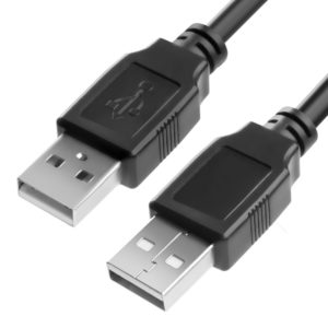
Tester power supply required: DC 5V/2A
This USB connector is additionally used when updating the tester.
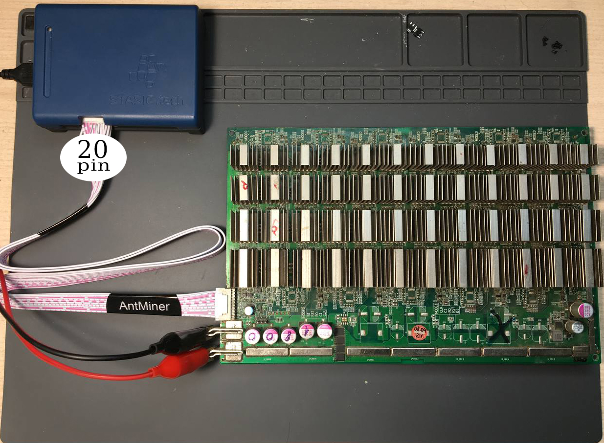
4. Hash board connection interface
Hash board connection interface STASIC 20 PIN
It is important! When working with the tester, it is allowed to use
ONLY LIVES AND ADAPTERS FROM THE DELIVERY SET!
Or self-made in accordance with the pinout provided by STASIC tech.
How to view tester ID STASIC tech?
Preparing for hash board diagnostics
1. Switching on the tester
Connect the tester to a DC 5V / 1-2A power source, USB 2.0 Type A cable (supplied),
the tester’s LED indicator will light up and a short beep will sound.
2. connecting to tester via Wi-Fi / updating tester
A) Open WiFi settings, list of wireless networks, on your device (PC/Laptop/Tablet/Smartphone)
B) Select in the list of wireless networks, a network called “Tester123“. Enter WiFi password: stasictester
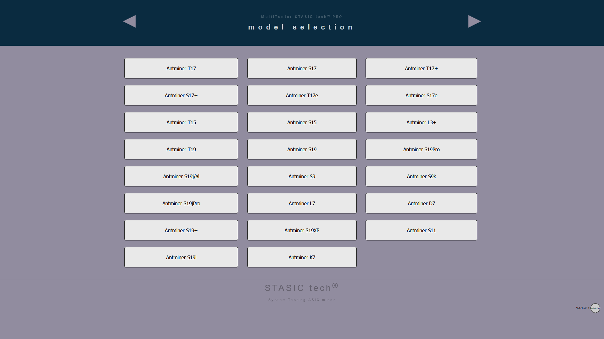
С) Open a browser, type in the address bar: 5.5.5.5/menu – the page for selecting models of supported boards of your version of the tester should appear on the screen.
check if your device (PC/Laptop/Tablet/Smartphone) is connected to the WiFi network of the tester? In the absence of the Internet in the WiFi network of the tester, some devices automatically reconnect to other networks with the presence of the Internet.
- The network addresses of your WiFi adapter can be entered manually, switch to automatically receive from DHCP in the network settings.
- You are trying to use your smartphone as a WiFi adapter to a PC, such a connection scheme will not allow you to work with the tester.
Instruction updating tester
3. Connecting the hash board to the tester
- Connect signal cable of tester to hashboard.
- Connect power supply (+\-) to hashboard.
- If tester is powered not from adapter, but for example from a USB computer or other device, then it must be grounded.
- The laboratory power supply (for powering hashboard) must be grounded.
ALGORITHM FOR DISCONNECTING TESTER FROM HASHBOARD:
- Turn off the hashboard power (+\-)
- Disconnect the tester signal cable from hashboard.
All of these steps will minimize the likelihood of exposure to potential differences between devices and eliminate the risk of damage to the tester.
 B. Supply appropriate power to the hash board. C. We go to the user interface, update the page (http://5.5.5.5/menu), select the hash board model in the browser. D. Select the correct model for diagnosis.
User interface
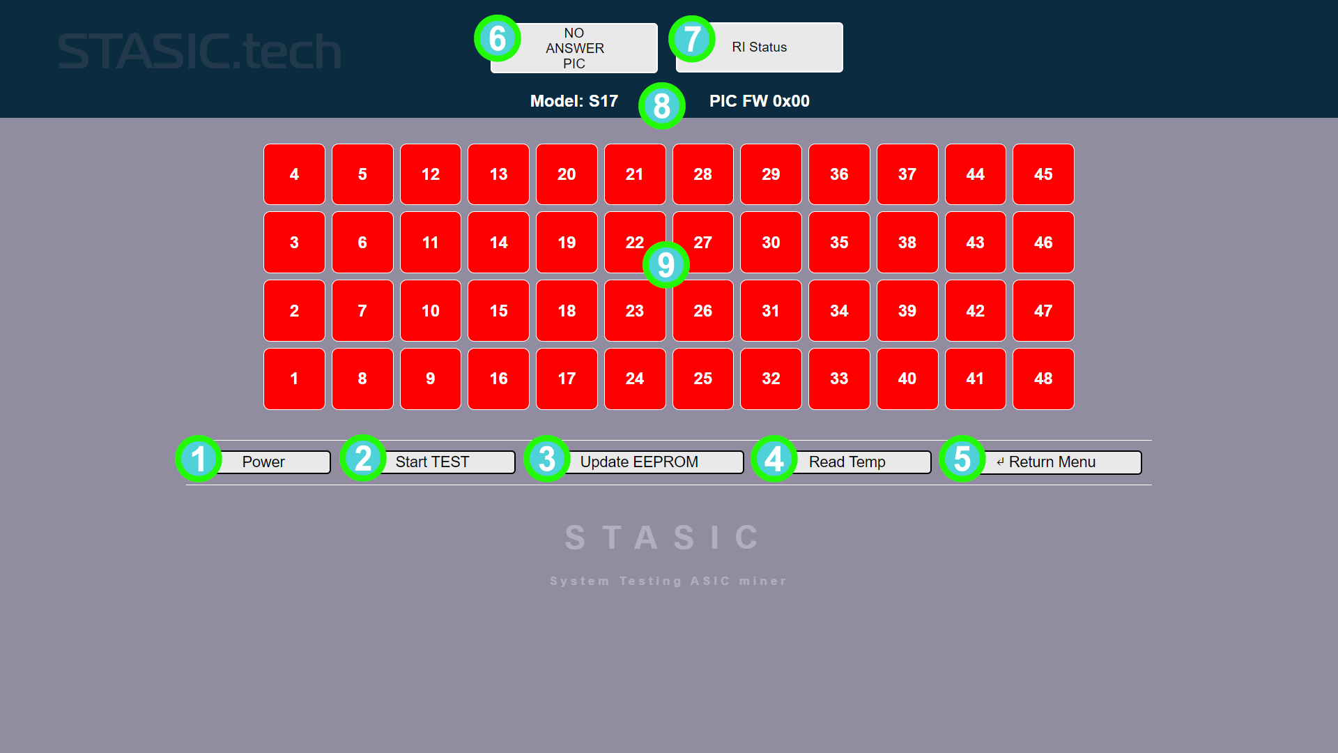
1. POWER
The “POWER” button is used to turn on / off the power of the hash board in manual mode, to measure the voltage of the hash board during diagnostics using additional equipment, a multimeter, an oscilloscope.
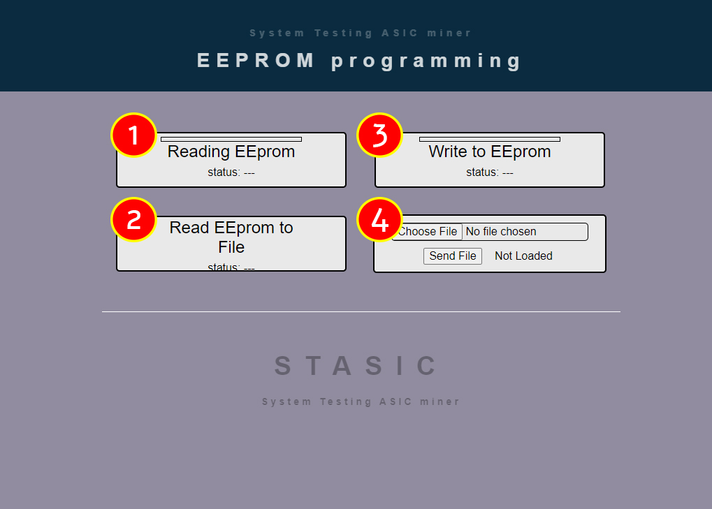
3. Update EEPROM
The “Update EEPROM” button is used to carry out operations with the firmware of the EEprom hash board.
Operations with EEprom
-
Reading Eeprom – reads the EEprom from the hash board into the tester’s memory.
-
Read Eeprom to File – reads the EEprom from the hash board, saving it to a file on the PC.
-
Write to Eeprom – Writes the EEprom dump, the last one stored in the tester’s memory, to the hash board..
-
Send File – Allows you to write a dump saved in a file on a PC to hash board EEprom..
IT IS IMPORTANT! To exit to the previous menu, always use the “RETURN MENU” button!! Management of the “arrows” of the browser is prohibited!

5. RETURN MENU
Button to return to the previous menu.
IT IS IMPORTANT! To exit to the previous menu, always use the “RETURN MENU” button!! Management of the “arrows” of the browser is prohibited!
7. RI signal indicator
Indicator of the presence of the corresponding signal on the hash board.
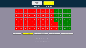
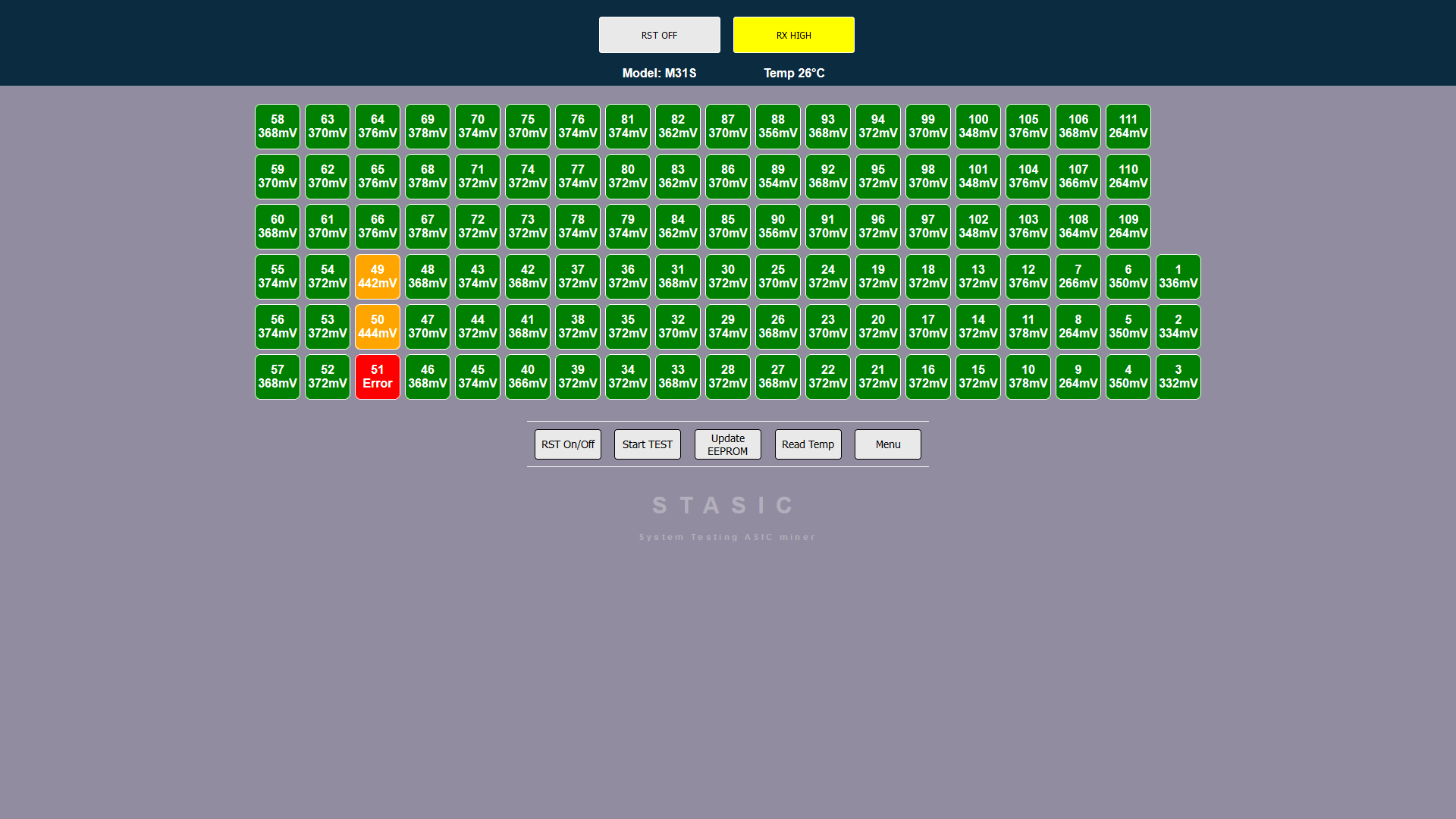
9. Graphic table of chip locations
Table for displaying information about the state and location of chips in the process of diagnosing a hash board.
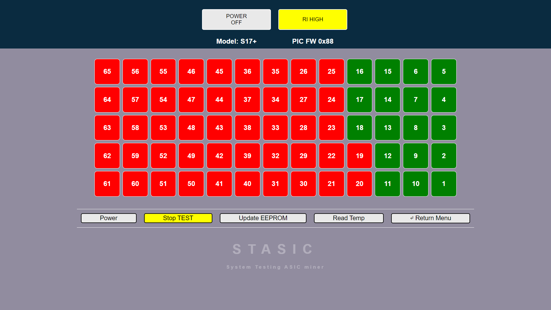
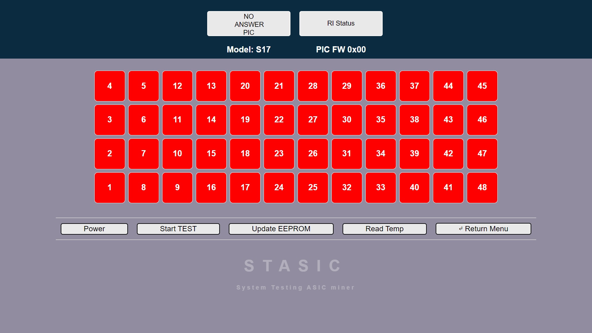
2. START TEST
The “START TEST” button enables/disables the function of automatic polling of the state of the hash board chips.
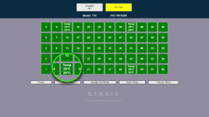
4. READ TEMP
The function of interrogating the temperature sensors of the hash board works only if the tester determines that all the chips of the hash board are in good condition.
6. POWER indicator
Power status indicator hash board
8. Additional Information
Information output line: Diagnosable hash board model, PIC controller version.
Additional diagnostic modules
Additional diagnostic software module Whatsminer+
ATTENTION! The tester power supply and the hash board power supply must be grounded!
ALGORITHM FOR CONNECTING HASH BOARD TO TESTER:
- We connect the signal cable of the tester to the hashboard.
- We connect power supply (+\-) to hashboard.
- If tester is powered not from power adapter, but, for example, from a USB computer or other device, then it must be grounded.
- The laboratory power supply (for powering the hashboard) must be grounded.
ALGORITHM FOR DISCONNECTING TESTER FROM HASH BOARD:
- Turn off power to hash board (+\-)
- Disconnect tester signal cable from hashboard.
All of these actions will minimize likelihood of exposure to potential differences and eliminate risk of damage to tester.
Chip voltage reading function Whatsminer
ATTENTION! for function to work, required power supply for hash board is 12-14 volts, 25 amperes,
A laboratory power supply is being used! PSU ASIC IS NOT SUITABLE!
When you press “Read Temp” button for first time, temperature of each chip is polled; when you press it again, information about voltage of each chip is displayed. The function helps diagnose Whatsminer malfunction – “Loss Balance”
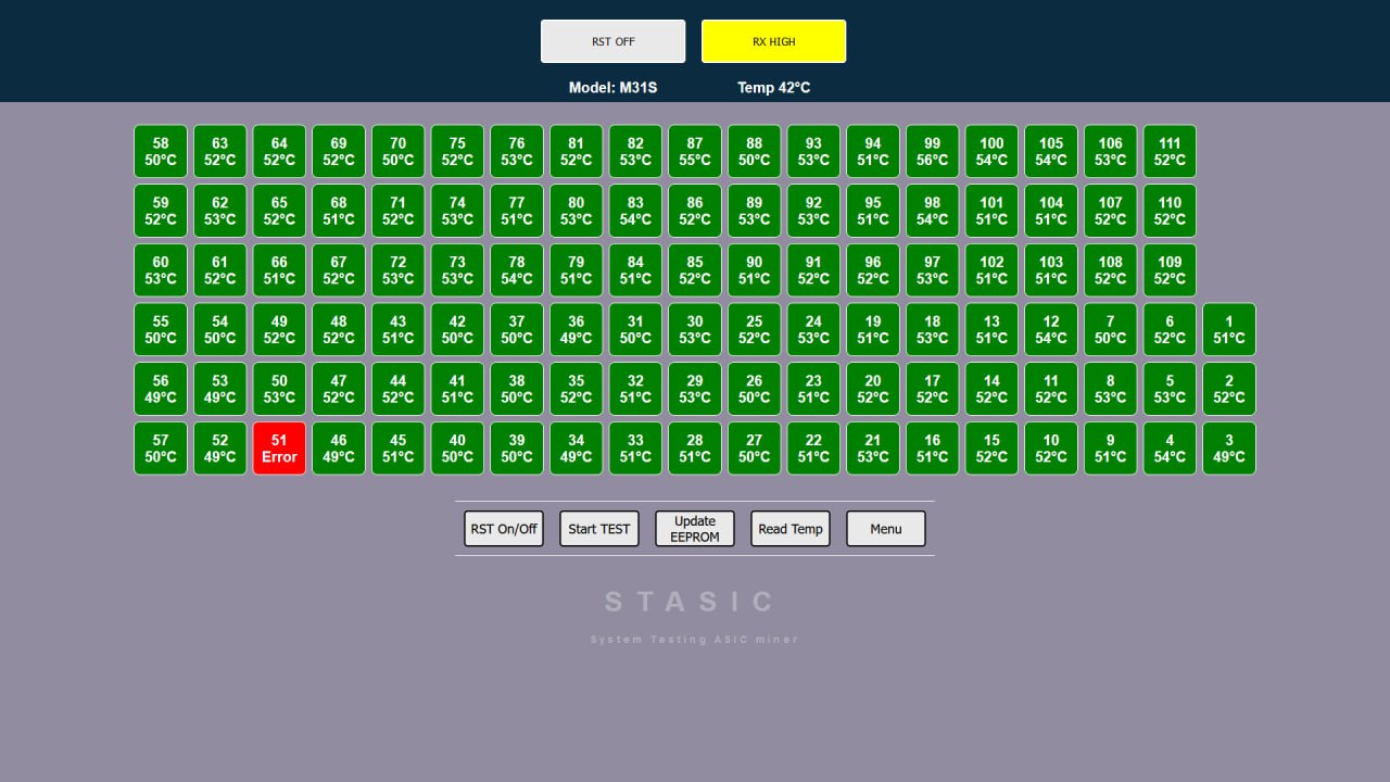
When diagnosing a Loss Balance error, you should pay attention to the voltage readings; on a fully operational board, the voltage readings will be in the same range. If you notice a difference of 90 mV or more, you should pay attention to it. We also conduct tests at different temperatures of the hash board, from room temperature to operating temperature of 60-70 degrees.
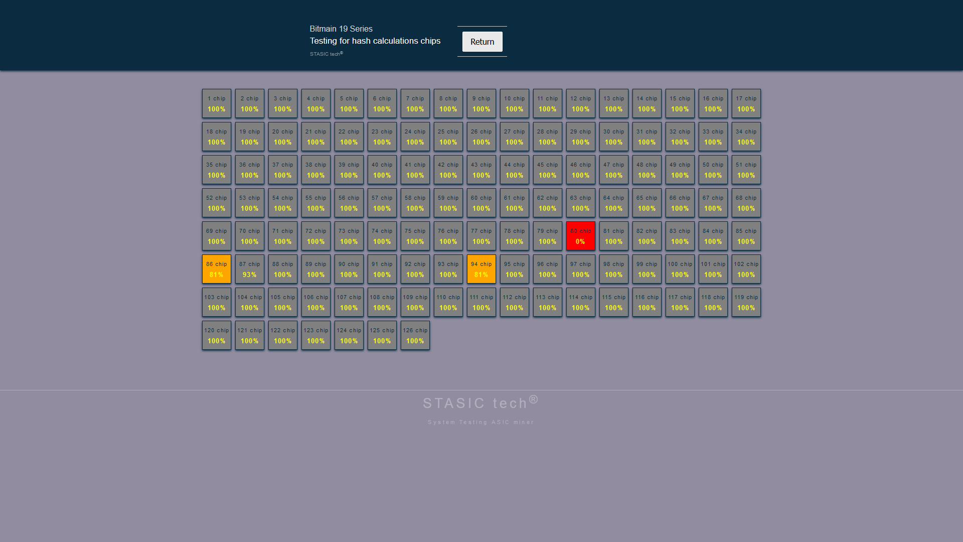
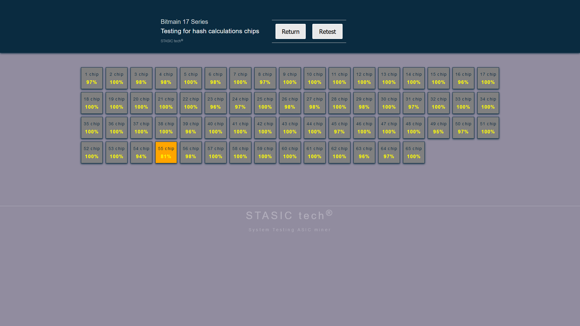
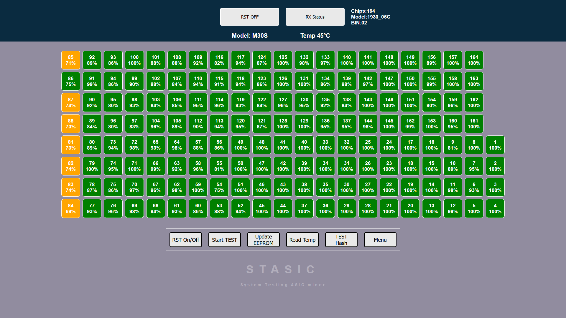
Hash calculation testing function (hash test)
ATTENTION! for function to work, required power supply for hash board is 12-14 volts, 30-75 amperes
(depending on board model and number of chips),
a laboratory power supply is being used!
When performing this test, monitor temperature of hash board, maintain same temperature of hash board each time you press HASH TEST button.
Additional diagnostic software module Antminer+
ATTENTION! The tester power supply and the hash board power supply must be grounded!
ALGORITHM FOR CONNECTING HASH BOARD TO TESTER:
- We connect the signal cable of the tester to the hashboard.
- We connect power supply (+\-) to hashboard.
- If tester is powered not from power adapter, but, for example, from a USB computer or other device, then it must be grounded.
- The laboratory power supply (for powering the hashboard) must be grounded.
ALGORITHM FOR DISCONNECTING TESTER FROM HASH BOARD:
- Turn off power to hash board (+\-)
- Disconnect tester signal cable from hashboard.
All of these actions will minimize likelihood of exposure to potential differences and eliminate risk of damage to tester.
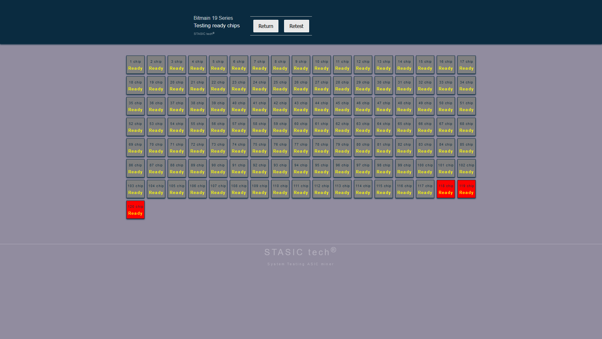
Antminer 17/19 series chip initialization function
ATTENTION! for function to work, a laboratory power supply is being used! PSU ASIC IS NOT SUITABLE!
The initialization function performs a procedure for checking readiness of chip core on hash board, similar to operation of ASIC control board before starting frequency overclocking process and starting mining process. Initialization is carried out on a completely repaired board on which, during a standard test in “START TEST” mode, all green chips are displayed, and temperature sensor readings are also correct. The function is started by pressing “READY CHIP” button
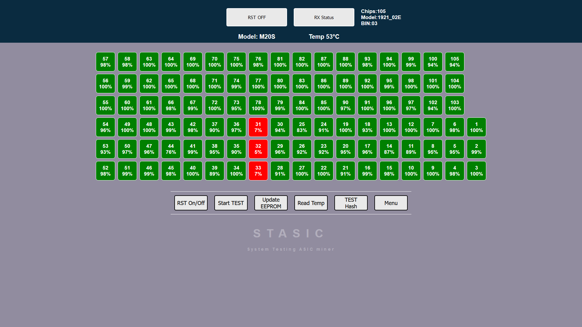
Hash calculation testing function (hash test) Antminer 17/19 series
ATTENTION! required current for the function to operate, 30-65 amperes
(depending on board model and number of chips),
A laboratory power supply is being used! PSU ASIC IS NOT SUITABLE!
Before performing a hash test, you must select frequency of chips by pressing “OVERCLOCK” button, each press increases frequency. To run one hash calculation test cycle, you need to click “HASH TEST” button.
When conducting this test, monitor temperature of hash board, remember that each time test is run, board consumes from 30 to 65 amps!
Maintain same temperature of hash board every time you press button “HASH TEST”.
If the board is severely overheated, some chips will appear red with a hash value of zero. Do not overheat the hash board by pressing the button frequently “HASH TEST“