Diagnostic complex STASIC tech® Avalon Finder
User’s Manual
STASIC tech PRO hardware and software system
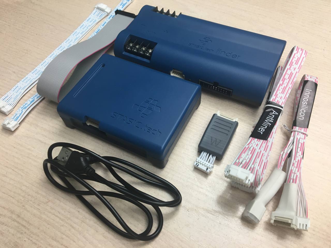
– Multi-tester hash board STASIC tech® Pro
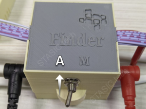
– Control unit STASIC tech® Finder (applies to Avalon only)
– data-cable 20/20 (to connect Finder to the tester)
– data-cable Avalon A10
– data-Cable Avalon A11/12
– data-cable Antminer
– data-cable Innosilicon
– adapter Whatsminer
Preparing to diagnose the hash board of the Avalon miner
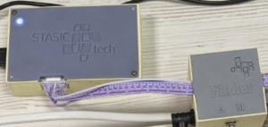
1. Connecting the Finder to the STASIC tech® Pro tester
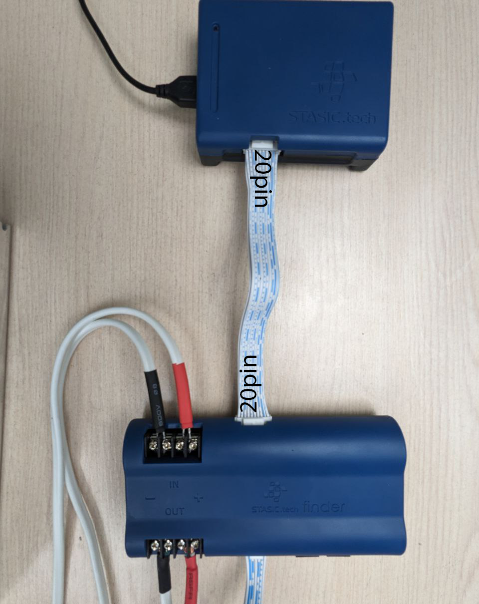
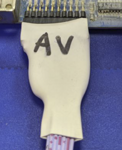
2. Connecting the data cable Avalon to the hashboard
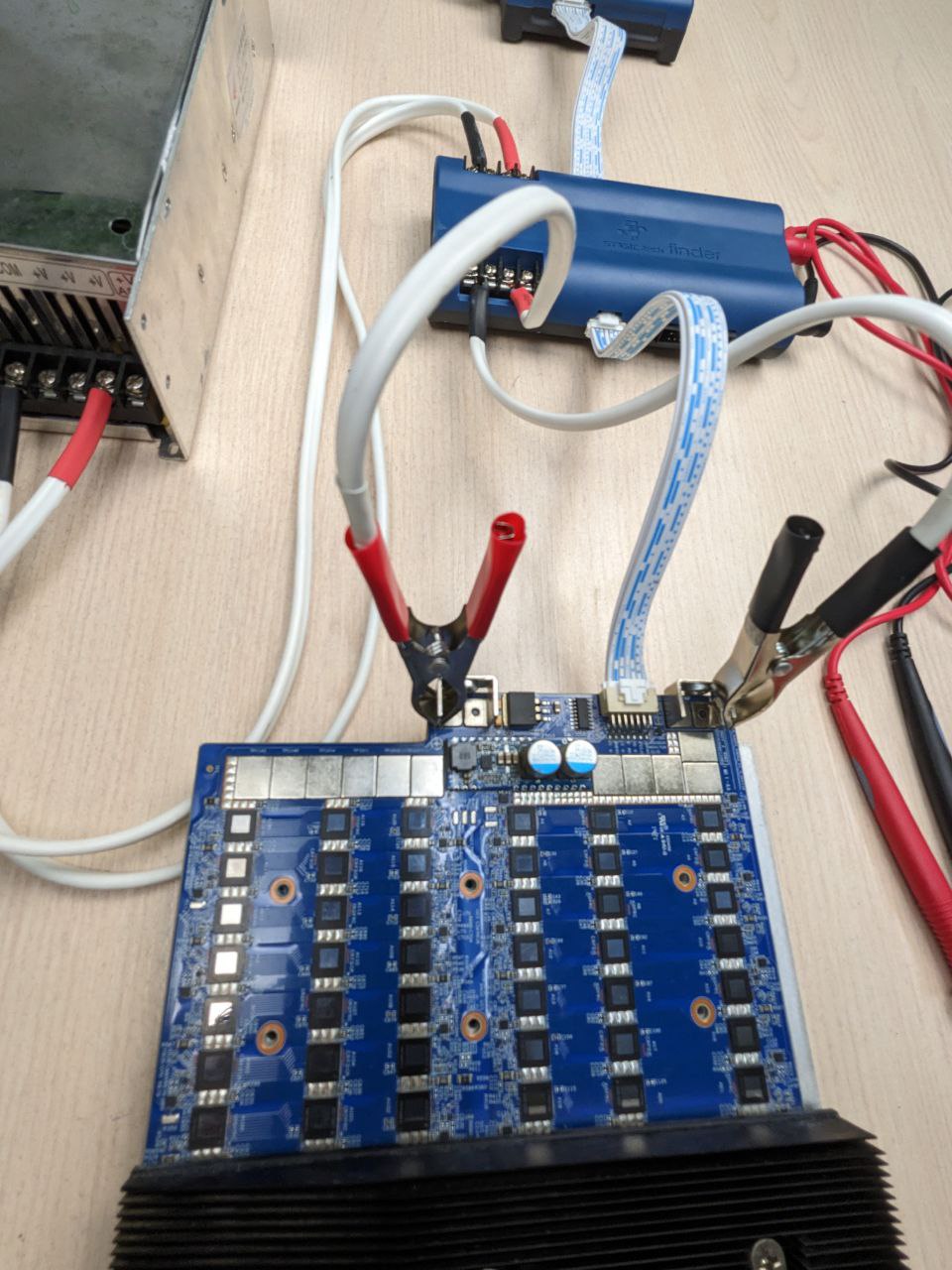
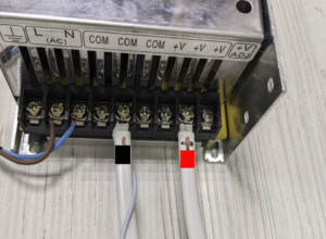
3. Connecting power wires to the power terminals of the hash board.
4. Connecting to the power supply
ATTENTION! Observe polarity!
To test the Avalon hash boards, you must use a laboratory power supply from 30A, test voltage NOT MORE THAN 12.6V.!!
Using the ASIC power supply to diagnose the hashboard may damage the STASIC tech® Avalon Finder and will not be covered by the warranty!!
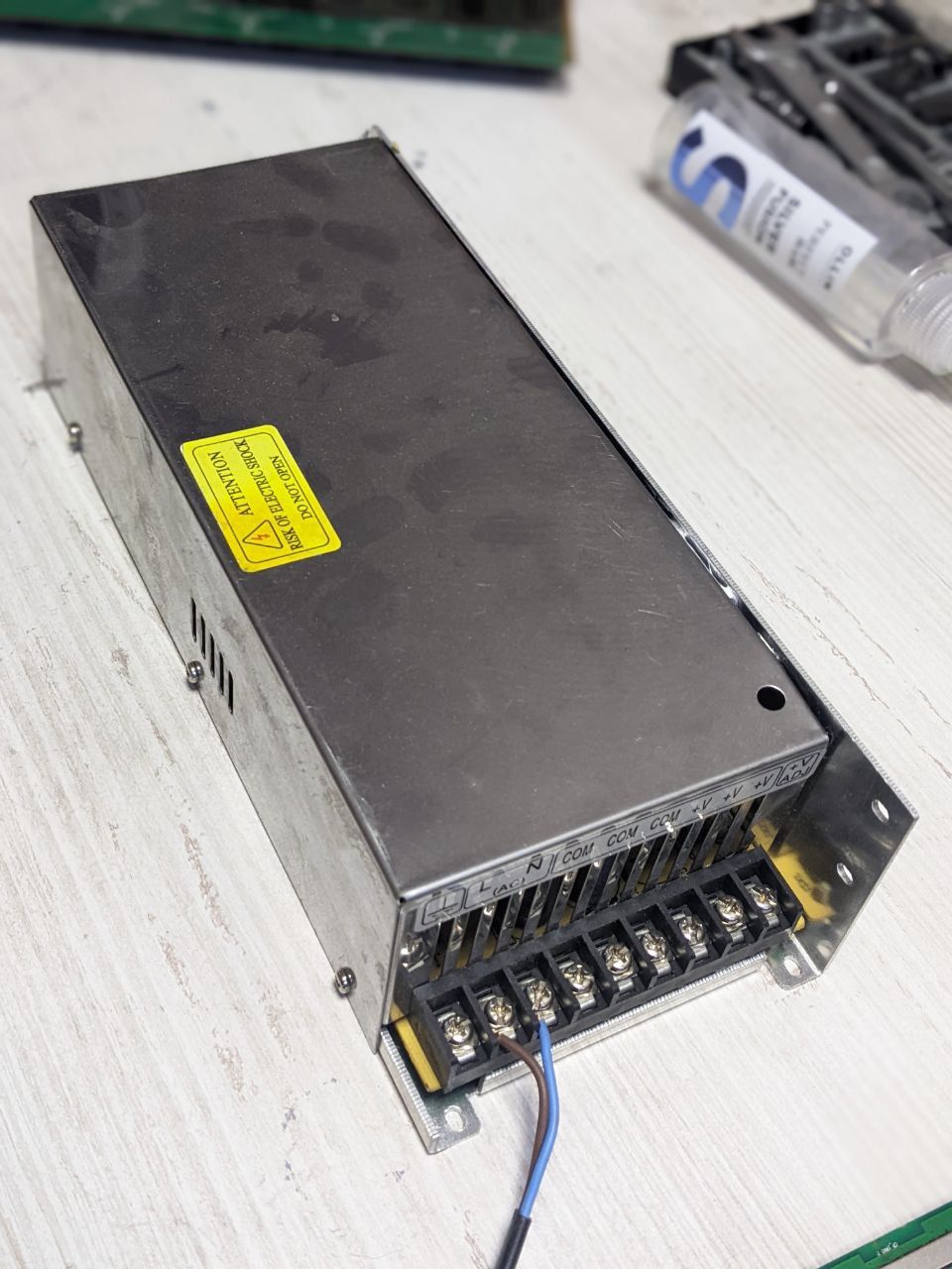
In the process of hash board testing, the STASIC tech® Avalon Finder hardware-software complex automatically regulates the power supply of the hash board, eliminating the rapid heating of the chips by the current consumed, which can significantly extend the time for diagnosing and testing the hash board.
Avalon miner hash board diagnostics
Diagnostics in automatic mode
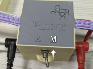
Switch STASIC tech® Finder to Automatic Diagnostic Mode
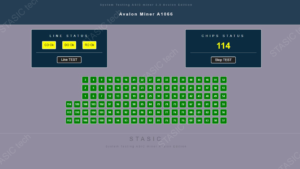
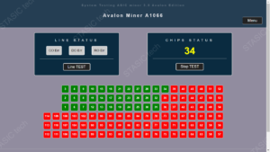
Hash board diagnostic window

The indication field “LINE STATUS” displays information about the integrity of the diagnosed lines of the hash board.

Indication field “CHIP STATUS” – Displays information about the number of responding chips on the hashboard.
Manual hash board diagnostics
Switch STASIC tech® Finder to Manual mode
 .
.
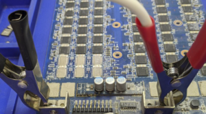
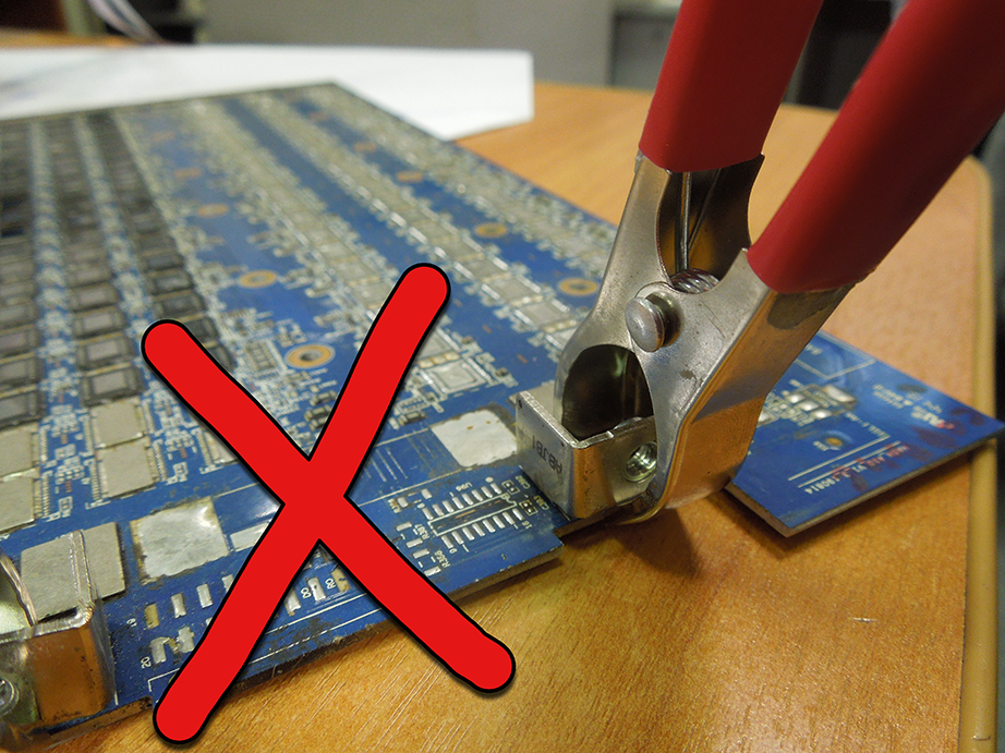
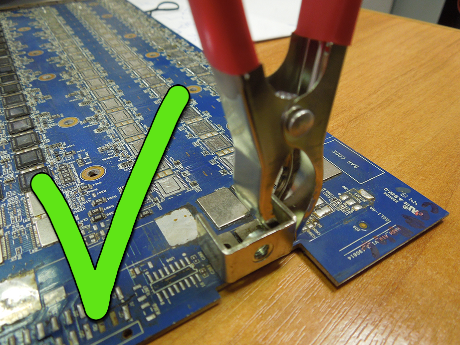
To identify a faulty chip or a break in one of the lines, use diagnostic probes.
1. Set the negative probe (black) to the mass of the domain being diagnosed.
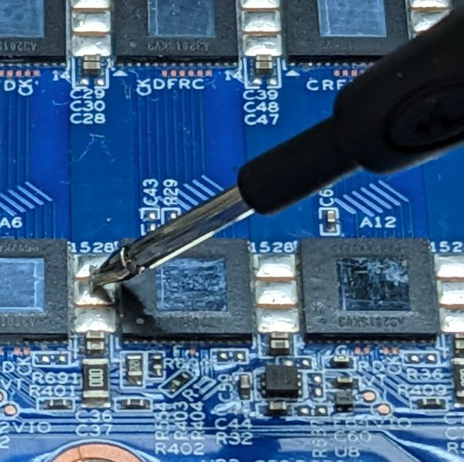
2. Positive probe (red) installed on the pad, signal “D”
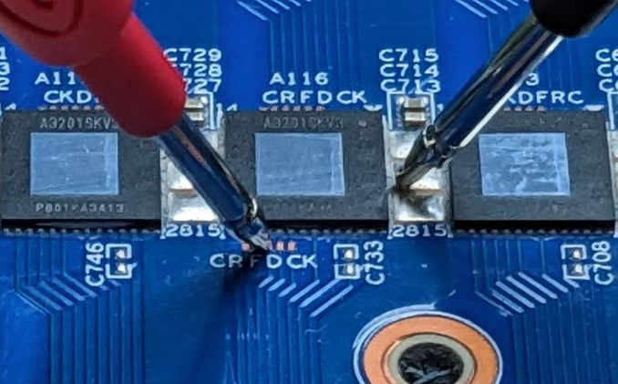
3. Start the test by pressing the “START TEST” button, the testing process is accompanied by sound signals from the tester. If it is necessary to check the lines, the “TEST LINE” button is additionally turned on
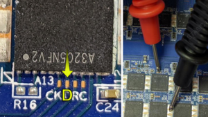
4. Closing with probes is carried out sequentially after each microcircuit, until a faulty one is detected.
5. Completes the testing process, the “STOP TEST” button